

OILFIELD SCALE CONTROL
High-Salinity Brine Scale Inhibitor: Set Up Continuous Injection
For a high-salinity brine, continuous scale-inhibitor selection starts with the water that will meet the chemical—not a generic freshwater test. Review calcium, barium, strontium, iron, sulfate, bicarbonate, salinity, temperature, pressure change and mixing ratio; then map the dilution water, injection point, first-contact concentration and time to the risk location. A clear bottle is only the first screen. If the water path has high temperature, long residence, restricted injection lines or a changing blend, use representative compatibility and dynamic confirmation before fixing the injection route or switching product family.
A continuous-injection scale inhibitor succeeds only when the chemistry reaches the scale-risk point in a stable, usable condition. In high-salinity oilfield brines, that means separating three questions that are often blended together: what mineral scale could form, whether the candidate and its dilution water remain compatible with the actual brine, and whether the injection geometry can deliver the chemistry before a pressure, temperature or mixing change creates risk. VCYCLETECH’s oilfield route lists WT-607 and WT-607B as product candidates for specific scale-control discussions. Neither name replaces representative brine screening, injection-route design or field verification. A clear operating map also helps distinguish a changed water path from a changed product route.
Define the scaling route before choosing the injection point
High salinity does not identify the mineral that is likely to deposit. Calcium, barium, strontium, sulfate, bicarbonate, iron, pH, temperature, pressure and the proportion of each water source decide what to investigate. A field can have more than one scale mechanism along the path: a blend can create a sulfate-scale risk upstream, while pressure loss or gas release shifts carbonate conditions later. This article owns the continuous-injection setup for an already identified high-salinity route; it is not a squeeze-treatment procurement guide or a post-failure deposit investigation.
Start with paired analyses of the water before and after mixing, not one averaged composition. Include expected seasonal or source changes. Mark where pressure drops, where water is heated or cooled, where gas separates and where solids first appear. Those locations determine how far upstream the inhibitor must be present and whether an injection point has enough mixing distance.
Use a brine screen that reflects first contact
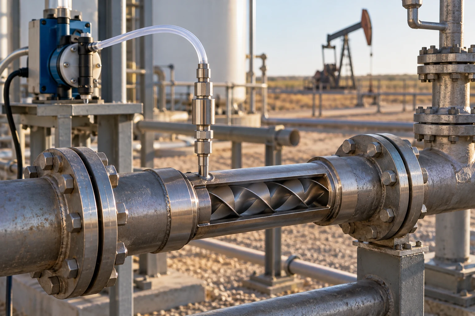
A candidate can appear acceptable after long dilution in a laboratory container yet behave differently when concentrated product first meets high-salinity brine in a small line, a dead leg or an injection quill. Screen the actual or representative brine with the intended dilution water and candidate chemistry. Observe more than visible haze: include phase separation, solids, viscosity or pumpability changes, and a sampling plan that distinguishes a local first-contact event from the bulk line.
Heriot-Watt’s scale-inhibitor selection work describes brine compatibility, thermal stability and carbonate/sulfate inhibition as separate laboratory screens for continuous and squeeze applications.1 That separation is useful: a clean compatibility result does not by itself establish inhibition at the relevant temperature or prove the selected feed point will protect the downstream line.
| Condition to check | Why it changes the route | Practical response |
|---|---|---|
| Actual brine plus proposed dilution water | Dilution can change first-contact conditions and local solubility. | Screen the pair at the planned mixing ratio; do not rely on a freshwater-only observation. |
| Ba/Sr/Ca, sulfate and bicarbonate with blend ratio | Different ions and water blends can move the scale mechanism. | Evaluate each source and the mixed water at the expected operating states. |
| Temperature, pressure and residence time | They influence precipitation risk and chemical stability along the route. | Use a thermal or dynamic confirmation that represents the risk location. |
| Restricted line, quill or low-flow first contact | Local concentration can be unlike the bulk process water. | Review injection point, mixing length and dilution sequence before changing the grade. |
| Iron-rich solids or carryover | Solids can complicate both deposition diagnosis and a compatibility result. | Check upstream separation/filtration and sample the relevant stream, not only a clean bottle. |

Design the injection path around mixing, not convenience
Choose the injection point from the first place scale risk can become active, then work upstream to find a location with reliable metering, safe access and enough mixing. A line that is convenient for a pump may be too close to a pressure change, too small for stable first contact or downstream of the location that needs protection. Long tiebacks, pressure and temperature variation, residence time and limited injection-line capacity are documented challenges for continuous applications.2
Sketch the chemical route separately from the water route: storage, transfer, optional dilution, pump, check valve, injection quill, mixer, process line and sample point. Every connection can change the candidate route. If a stability issue appears only at the quill or a response arrives too late at the risk location, alter dilution, injection position or mixing design before assuming the active chemistry is the wrong family.
Use the oilfield water-treatment application to connect scale risk with delivery route. Current relevant product pages include WT-607 for oilfield refill-water discussions and WT-607B for barium/strontium scale discussions. The ATMP handling video provides product-handling context. The older brine-compatibility and squeeze-trial guide remains the right page for a procurement/squeeze brief; the produced-water scale investigation is the right page when a deposit is already on the asset.
Verify the route under conditions that can fail in service
Move from a bench screen to a dynamic or circulating confirmation when pressure, temperature, residence time, solids or changing source water are central to the risk. The confirmation does not need to copy every field detail; it needs to challenge the mechanism that could make the route fail. For example, use the relevant brine, intended dilution water, temperature window and contact time, then test the water at the point where the inhibitor must still be useful.
Once the route is in service, trend the indicators tied to the original decision: scale-risk chemistry, injection reliability, residual method where validated for the product, differential pressure, deposits, water analysis and key operating changes. Review a departure from trend alongside source blend, temperature, pressure and injection-path changes. This avoids declaring a chemistry failure when the actual cause is a stopped pump, altered dilution source or new mixing condition.
For a scoped discussion, share individual water and blend analyses, expected ratios, temperatures and pressures, line drawing, dilution water, pump and injection details, historical deposits or scale risk, and the target point to protect. Discuss your continuous-injection route →
Separate a chemistry issue from a route change
When a well or surface line begins to show a new scale signal, first ask what has changed in the route. A new source-water proportion can alter saturation conditions. A different dilution source can alter first contact. A pump service interval, check-valve problem, line restriction or moved quill can change the amount of chemistry reaching the risk point even though the product name has not changed. These are operational changes worth checking before an otherwise suitable chemistry family is replaced.
Keep an injection record that can be compared with the process record: product identity, intended dilution medium, pump status, injection point, line pressure, flow indication and any interruption. Pair it with the water and operating values that affect the scale mechanism. The aim is not to produce a universal alarm value; it is to make a change in the physical delivery path visible. A short trend showing brine blend, temperature, pressure and feed reliability is often more useful than a one-time bottle test taken after the problem has already developed.
If the risk location moves because a blend point, pressure transition or operating temperature changes, revisit the design upstream. The appropriate response may be a new injection point or mixing sequence, a more representative dynamic screen, upstream solids management or a different candidate chemistry. Treating every trend deviation by raising a feed rate hides those options and can make the later diagnosis harder.
Frequently asked questions
Is a clear bottle test enough to approve a continuous injection route?
No. It is a useful first compatibility screen, but it does not demonstrate inhibitor performance, local first-contact behavior, thermal stability or protection at the actual scale-risk location.
Why test dilution water as well as brine?
The proposed dilution water can change the first-contact environment before the chemistry is dispersed in the process brine. Include it in the screen and in the injection-path review.
Can WT-607 or WT-607B be selected from barium or strontium alone?
No. Those current product pages establish relevant discussion routes, while final selection depends on the full brine, scale mechanism, operating conditions, compatibility and delivery path.
When should I change the injection point instead of changing chemistry?
Review injection position when the candidate is stable in representative water but cannot reach the risk point, sees poor mixing, meets a local concentrated first contact or arrives after a key pressure/temperature transition.
What information is most useful for an injection-route review?
Provide individual and blended water analyses, temperatures, pressures, flow and residence time, expected source changes, dilution water, injection-line drawing, pump/quill details, deposit history and the target protection location.
Sources
- Heriot-Watt University, Scale inhibitor selection for continuous and downhole squeeze application — distinct brine-compatibility, thermal-stability and scale-inhibition screening context.
- SLB, Scale Deposition Control and Management in Subsea Fields — continuous-injection challenges including injection lines, tiebacks, pressure/temperature variation and residence time.
- SLB, Scale Inhibitors for Clear Brines — brine-specific scale-control product-category context.
Sources checked 26 September 2026. Field brine, temperature, pressure, mixing and exact product conditions still govern the final route.